Article Purpose
This article serves as a detailed discussion on implementing image edge detection through pixel neighbourhood maximum and minimum value subtraction. Additional concepts illustrated in this article include implementing a median filter and RGB grayscale conversion.
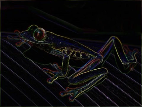
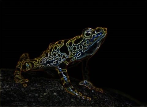
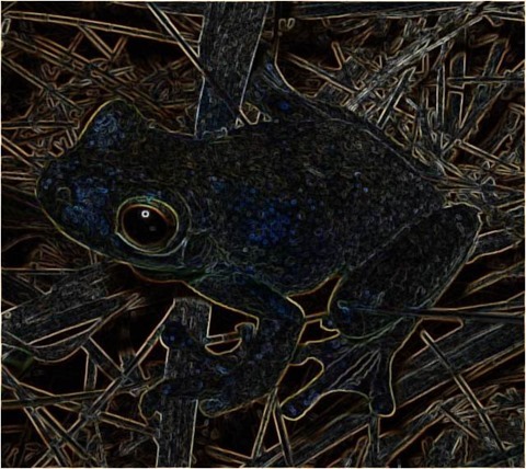
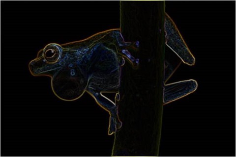
Frog Filter 3×3 Smoothed
Sample Source Code
This article is accompanied by a sample source code Visual Studio project which is available for download here.
Using the Sample Application
This article’s accompanying sample source code includes a Windows Forms based sample application. The sample application provides an implementation of the concepts explored by this article. Concepts discussed can be easily replicated and tested by using the sample application.
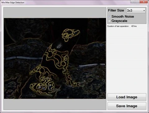
Source/input image files can be specified from the local file system when clicking the Load Image button. Additionally users also have the option to save resulting filtered images by clicking the Save Image button.
The sample application user interface enables the user to specify three filter configuration values. These values serve as input parameters to the Min/Max Edge Detection Filter and can be described as follows:
- Filter Size – Determines the number of surrounding pixels to consider when calculating the minimum and maximum pixel values. This value equates to the size of a pixel’s neighbourhood of pixels. When gradient edges expressed in a source image requires a higher or lower level of expression in result images the filter size value should be adjusted. Higher Filter Size values result in gradient edges being expressed at greater intensity levels in resulting images. Inversely, lower Filter Size values delivers the opposite result of gradient edges being expressed at lesser intensity levels.
- Smooth Noise – Image noise when present in source images, can to varying degrees affect the Min/Max Edge Detection Filter’s accuracy in calculating gradient edges. In order to reduce the negative affects of source image noise an image smoothing filter may be implemented. Smoothing out image noise requires additional filter processing and therefore requires additional computation time. If source images reflect minor or no image noise, additional image smoothing may be excluded to reduce filter processing duration.
- Grayscale – When required, result images can be expressed in grayscale through configuring this value.
The following image represents a screenshot of the Min/Max Edge Detection Sample application in action.
Min/Max Edge Detection
The method of edge detection illustrated in this article can be classified as a variation of commonly implemented edge detection methods. Image edges expressed within a source image can be determined through the presence of sudden and significant changes in gradient levels that occur within a small/limited perimeter.
As a means to determine gradient level changes the Min/Max Edge Detection algorithm performs pixel neighbourhood inspection, comparing maximum and minimum colour channel values. Should the difference between maximum and minimum colour values be significant, it would be an indication of a significant change in gradient level within the pixel neighbourhood being inspected.
Image noise represents interference in relation to regular gradient level expression. Image noise does not signal the presence of an image edge, although could potentially result in incorrectly determining image edge presence. Image noise and the negative impact thereof can be significantly reduced when applying image smoothing, also sometimes referred to as image blur. The Min/Max Edge Detection algorithm makes provision for optional image smoothing implemented in the form of a median filter.
The following sections provide more detail regarding the concepts introduced in this section, pixel neighbourhood and median filter.
Frog Filter 3×3 Smoothed
Pixel Neighbourhood
A pixel neighbourhood refers to a set of pixels, all of which are related through pixel location coordinates. The width and height of a pixel neighbourhood must be equal, in other words, a pixel neighbourhood can only be square. Additionally, the width/height of a pixel neighbourhood must be an uneven value. When inspecting a pixel’s neighbouring pixels, the pixel being inspected will always be located at the exact center of the pixel neighbourhood. Only when a pixel neighbourhood’s width/height are an uneven value can such a pixel neighbourhood have an exact center pixel. Each pixel represented in an image has a different set of neighbours, some neighbours overlap, but no two pixels have the exact same neighbours. A pixel’s neighbouring pixels can be determined when considering the pixel to be at the center of a block of pixels, extending half the neighbourhood size less one in horizontal, vertical and diagonal directions.
Median Filter
In context of this article and the Min/Max Edge Detection filter, median filtering has been implemented as a means to reduce source image noise. From the Median Wikipedia page we gain the following quote:
In statistics and probability theory, the median is the number separating the higher half of a data sample, a population, or a probability distribution, from the lower half. The median of a finite list of numbers can be found by arranging all the observations from lowest value to highest value and picking the middle one (e.g., the median of {3, 3, 5, 9, 11} is 5).
Frog Filter 3×3 Smoothed
The application of a median filter is based in the concept of pixel neighbourhood as discussed earlier. The implementation steps required when applying a median filter can be described as follows:
- Iterate every pixel. The pixel neighbourhood of each pixel in a source image needs to be determined and inspected.
- Order/Sort pixel neighbourhood values. Once a pixel neighbourhood for a specific pixel has been determined the values expressed by all the pixels in that neighbourhood needs to be sorted or ordered according to value.
- Determine midpoint value. In relation to the sorted pixel neighbourhood values, the value positioned exactly halfway between first and last value needs to be determined. As an example, if a pixel neighbourhood contains a total of nine pixels, the midpoint would be at position number five, which is four positions from the first and last value inclusive. The midpoint value in a sorted range of neighbourhood pixel values, is the median value of that pixel neighbourhood’s values.
The median filter should not be confused with the mean filter. A median will always be a midpoint value from a sorted value range, whereas a mean value is equal to the calculated average of a value range. The median filter has the characteristic of reducing image noise whilst still preserving image edges. The mean filter will also reduce image noise, but will do so through generalized image blurring, also referred to as box blur, which does not preserve image edges.
Note that when applying a median filter to RGB colour images median values need to be determined per individual colour channel.
Frog Filter 3×3 Smoothed
Min/Max Edge Detection Algorithm
Image edge detection based in a min/max approach requires relatively few steps, which can be combined in source code implementations to be more efficient from a computational/processing perspective. A higher level logical definition of the steps required can be described as follows:
- Image Noise Reduction – If image noise reduction is required apply a median filter to the source image.
- Iterate through all of the pixels contained within an image.
- For each pixel being iterated, determine the neighbouring pixels. The pixel neighbourhood size will be determined by the specified filter size.
- Determine the Minimum and Maximum pixel value expressed within the pixel neighbourhood.
- Subtract the Minimum from the Maximum value and assign the result to the pixel currently being iterated.
- Apply Grayscale conversion to the pixel currently being iterated, only if grayscale conversion had been configured.
Implementing a Min/Max Edge Detection Filter
The source code implementation of the Min/Max Edge Detection Filter declares two methods, a median filter method and an edge detection method. A median filter and edge detection filter cannot be processed simultaneously. When applying a median filter, the median value of a pixel neighbourhood determined from a source image should be expressed in a separate result image. The original source image should not be altered whilst inspecting pixel neighbourhoods and calculating median values. Only once all pixel values in the result image has been set, can the result image serve as a source image to an edge detection filter method.
The following code snippet provides the source code definition of the MedianFilter method.
private static byte[] MedianFilter(this byte[] pixelBuffer,
                                    int imageWidth,
                                    int imageHeight,
                                    int filterSize)
{
    byte[] resultBuffer = new byte[pixelBuffer.Length];

    int filterOffset = (filterSize - 1) / 2;
    int calcOffset = 0;
    int stride = imageWidth * pixelByteCount;

    int byteOffset = 0;
    var neighbourCount = filterSize * filterSize;
    int medianIndex = neighbourCount / 2;

    var blueNeighbours = new byte[neighbourCount];
    var greenNeighbours = new byte[neighbourCount];
    var redNeighbours = new byte[neighbourCount];

    for (int offsetY = filterOffset; offsetY <
        imageHeight - filterOffset; offsetY++)
    {
        for (int offsetX = filterOffset; offsetX <
            imageWidth - filterOffset; offsetX++)
        {
            byteOffset = offsetY *
                            stride +
                            offsetX * pixelByteCount;

            for (int filterY = -filterOffset, neighbour = 0;
                filterY <= filterOffset; filterY++)
            {
                for (int filterX = -filterOffset;
                    filterX <= filterOffset; filterX++, neighbour++)
                {
                    calcOffset = byteOffset +
                                    (filterX * pixelByteCount) +
                                    (filterY * stride);

                    blueNeighbours[neighbour] = pixelBuffer[calcOffset];
                    greenNeighbours[neighbour] = pixelBuffer[calcOffset + greenOffset];
                    redNeighbours[neighbour] = pixelBuffer[calcOffset + redOffset];
                }
            }

            Array.Sort(blueNeighbours);
            Array.Sort(greenNeighbours);
            Array.Sort(redNeighbours);

            resultBuffer[byteOffset] = blueNeighbours[medianIndex];
            resultBuffer[byteOffset + greenOffset] = greenNeighbours[medianIndex];
            resultBuffer[byteOffset + redOffset] = redNeighbours[medianIndex];
            resultBuffer[byteOffset + alphaOffset] = maxByteValue;
        }
    }

    return resultBuffer;
}
Notice the definition of three separate byte arrays, each intended to represent a pixel neighbourhood’s pixel values related to a specific colour channel. Each neighbourhood colour channel byte array needs to be sorted according to value. The value located at the array index exactly halfway from the start and the end of the array represents the median value. When a median value has been determined, the result buffer pixel related to the source buffer pixel in terms of XY Location needs to be set.
Frog Filter 3×3 Smoothed
The sample source code defines two overloaded versions of an edge detection method. The first version is defined as an extension method targeting the Bitmap class. A FilterSize parameter is the only required parameter, intended to specify pixel neighbourhood width/height. In addition, when invoking this method optional parameters may be specified. When image noise reduction should be implemented the smoothNoise parameter should be defined as true. If resulting images are required in grayscale the last parameter, grayscale, should reflect true. The following code snippet provides the definition of the MinMaxEdgeDetection method.
public static Bitmap MinMaxEdgeDetection(this Bitmap sourceBitmap,
                                            int filterSize,
                                            bool smoothNoise = false,
                                            bool grayscale = false)
{
    return sourceBitmap.ToPixelBuffer()
                        .MinMaxEdgeDetection(sourceBitmap.Width,
                                            sourceBitmap.Height,
                                            filterSize,
                                            smoothNoise,
                                            grayscale)
                        .ToBitmap(sourceBitmap.Width,
                                    sourceBitmap.Height);
}
The MinMaxEdgeDetection method as expressed above essentially acts as a wrapper method, invoking the overloaded version of this method, performing mapping between Bitmap objects and byte array pixel buffers.
An overloaded version of the MinMaxEdgeDetection method performs all of the tasks required in edge detection through means of minimum maximum pixel neighbourhood value subtraction. The method definition as provided by the following code snippet.
private static byte[] MinMaxEdgeDetection(this byte[] sourceBuffer,
                                          int imageWidth,
                                          int imageHeight,
                                          int filterSize,
                                          bool smoothNoise = false,
                                          bool grayscale = false)
{
    byte[] pixelBuffer = sourceBuffer;

    if (smoothNoise)
    {
        pixelBuffer = sourceBuffer.MedianFilter(imageWidth,
                                                imageHeight,
                                                filterSize);
    }

    byte[] resultBuffer = new byte[pixelBuffer.Length];

    int filterOffset = (filterSize - 1) / 2;
    int calcOffset = 0;
    int stride = imageWidth * pixelByteCount;

    int byteOffset = 0;

    byte minBlue = 0, minGreen = 0, minRed = 0;
    byte maxBlue = 0, maxGreen = 0, maxRed = 0;

    for (int offsetY = filterOffset; offsetY <
        imageHeight - filterOffset; offsetY++)
    {
        for (int offsetX = filterOffset; offsetX <
            imageWidth - filterOffset; offsetX++)
        {
            byteOffset = offsetY *
                            stride +
                            offsetX * pixelByteCount;

            minBlue = maxByteValue;
            minGreen = maxByteValue;
            minRed = maxByteValue;

            maxBlue = minByteValue;
            maxGreen = minByteValue;
            maxRed = minByteValue;

            for (int filterY = -filterOffset;
                filterY <= filterOffset; filterY++)
            {
                for (int filterX = -filterOffset;
                    filterX <= filterOffset; filterX++)
                {
                    calcOffset = byteOffset +
                                    (filterX * pixelByteCount) +
                                    (filterY * stride);

                    minBlue = Math.Min(pixelBuffer[calcOffset], minBlue);
                    maxBlue = Math.Max(pixelBuffer[calcOffset], maxBlue);

                    minGreen = Math.Min(pixelBuffer[calcOffset + greenOffset], minGreen);
                    maxGreen = Math.Max(pixelBuffer[calcOffset + greenOffset], maxGreen);

                    minRed = Math.Min(pixelBuffer[calcOffset + redOffset], minRed);
                    maxRed = Math.Max(pixelBuffer[calcOffset + redOffset], maxRed);
                }
            }

            if (grayscale)
            {
                resultBuffer[byteOffset] = ByteVal((maxBlue - minBlue) * 0.114 +
                                                    (maxGreen - minGreen) * 0.587 +
                                                    (maxRed - minRed) * 0.299);

                resultBuffer[byteOffset + greenOffset] = resultBuffer[byteOffset];
                resultBuffer[byteOffset + redOffset] = resultBuffer[byteOffset];
                resultBuffer[byteOffset + alphaOffset] = maxByteValue;
            }
            else
            {
                resultBuffer[byteOffset] = (byte)(maxBlue - minBlue);
                resultBuffer[byteOffset + greenOffset] = (byte)(maxGreen - minGreen);
                resultBuffer[byteOffset + redOffset] = (byte)(maxRed - minRed);
                resultBuffer[byteOffset + alphaOffset] = maxByteValue;
            }
        }
    }

    return resultBuffer;
}
As discussed earlier, image noise reduction if required should be the first task performed. Based on parameter value the method applies a median filter to the source image buffer.
When iterating a pixel neighbourhood a comparison is performed between the currently iterated neighbouring pixel’s value and the previously determined minimum and maximum values.
When the grayscale method parameter reflects true, a grayscale algorithm is applied to the difference between the determined maximum and minimum pixel neighbourhood values.
Should the grayscale method parameter reflect false, grayscale algorithm logic will not execute. Instead, the result obtained from subtracting the determined minimum and maximum values are assigned to the relevant pixel and colour channel on the result buffer image.
Frog Filter 3×3 Smoothed
Sample Images
This article features several sample images provided as examples. All sample images were created using the sample application. All of the original source images used in generating sample images have been licensed by their respective authors to allow for reproduction here. The following section lists each original source image and related license and copyright details.
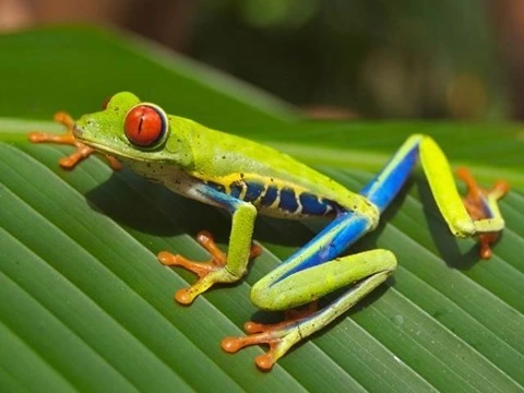
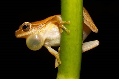
Red-eyed Tree Frog (Agalychnis callidryas), photographed near Playa Jaco in Costa Rica © 2007 Careyjamesbalboa (Carey James Balboa) has been released into the public domain by the author.
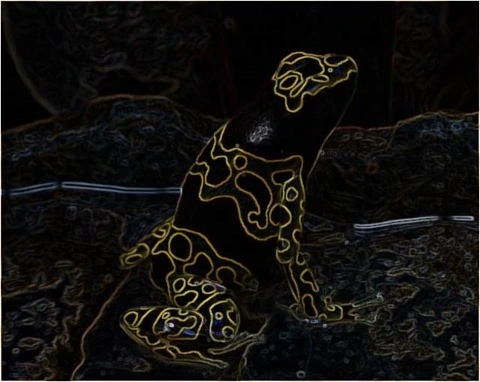
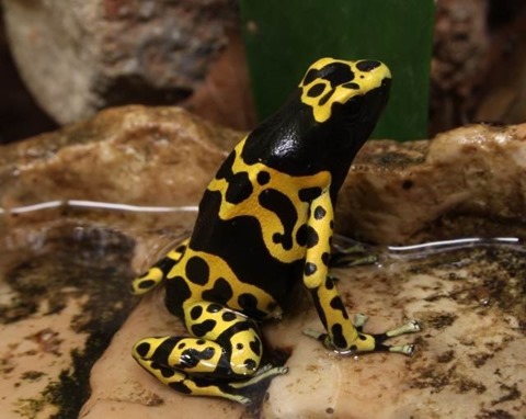
Yellow-Banded Poison Dart Frog © 2013 H. Krisp is used here under a Creative Commons Attribution 3.0 Unported license.
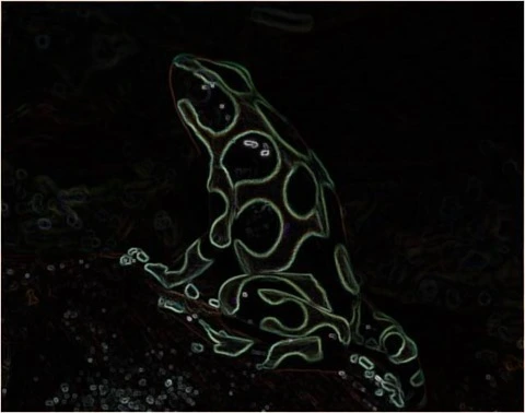
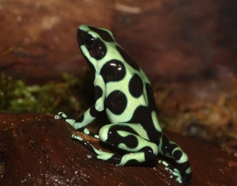
Green and Black Poison Dart Frog © 2011 H. Krisp is used here under a Creative Commons Attribution 3.0 Unported license.
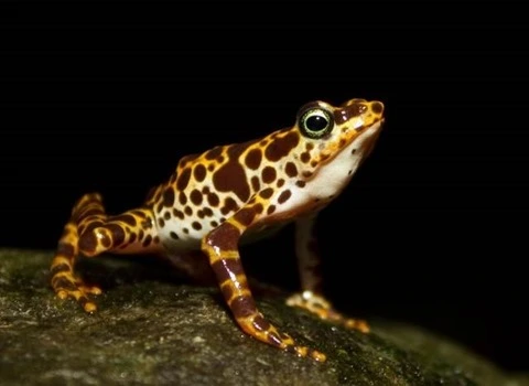
Atelopus certus calling male © 2010 Brian Gratwicke is used here under a Creative Commons Attribution 2.0 Generic license.
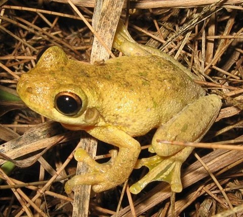
Tyler’s Tree Frog (Litoria tyleri) © 2006 LiquidGhoul has been released into the public domain by the author.
Dendropsophus microcephalus © 2010 Brian Gratwicke is used here under a Creative Commons Attribution 2.0 Generic license.
Related Articles and Feedback
Feedback and questions are always encouraged. If you know of an alternative implementation or have ideas on a more efficient implementation please share in the comments section.
I’ve published a number of articles related to imaging and images of which you can find URL links here:
- C# How to: Image filtering by directly manipulating Pixel ARGB values
- C# How to: Image filtering implemented using a ColorMatrix
- C# How to: Blending Bitmap images using colour filters
- C# How to: Bitmap Colour Substitution implementing thresholds
- C# How to: Generating Icons from Images
- C# How to: Swapping Bitmap ARGB Colour Channels
- C# How to: Bitmap Pixel manipulation using LINQ Queries
- C# How to: Linq to Bitmaps – Partial Colour Inversion
- C# How to: Bitmap Colour Balance
- C# How to: Bi-tonal Bitmaps
- C# How to: Bitmap Colour Tint
- C# How to: Bitmap Colour Shading
- C# How to: Image Solarise
- C# How to: Image Contrast
- C# How to: Bitwise Bitmap Blending
- C# How to: Image Arithmetic
- C# How to: Image Convolution
- C# How to: Image Edge Detection
- C# How to: Difference Of Gaussians
- C# How to: Image Median Filter
- C# How to: Image Unsharp Mask
- C# How to: Image Colour Average
- C# How to: Image Erosion and Dilation
- C# How to: Morphological Edge Detection
- C# How to: Boolean Edge Detection
- C# How to: Gradient Based Edge Detection
- C# How to: Sharpen Edge Detection
- C# How to: Image Cartoon Effect
- C# How to: Calculating Gaussian Kernels
- C# How to: Image Blur
- C# How to: Image Transform Rotate
- C# How to: Image Transform Shear
- C# How to: Compass Edge Detection
- C# How to: Oil Painting and Cartoon Filter
- C# How to: Stained Glass Image Filter
- C# How to: Image ASCII Art
- C# How to: Weighted Difference of Gaussians
- C# How to: Image Boundary Extraction
- C# How to: Image Abstract Colours Filter
- C# How to: Fuzzy Blur Filter
Filed under: Augmented Reality, C#, Code Samples, Edge Detection, Extension Methods, Graphic Filters, Graphics, How to, Image Arithmetic, Image Filtering, Image Filters, Image Processing, Image Transform, Opensource Tagged: Alpha Red Green Blue, Augmented Reality, Binary Image, Bitmap ARGB, Bitmap Filters, Bitmap.LockBits, BitmapData, Blur, C#, Code Sample, Color Filters, Computer vision, Converting Images, Edge Detection, Extension Methods, Graphic Filters, How to, Image, Image Intensity, Image Manipulation, Image noise reduction, Image processing, Image Transform, Machine vision, Median Filter, Pixel Filters, Pixel Neighbourhood Max, Pixel Neighbourhood Min
